The 3-axis method is slower compared to the 4th axis method because the latter allows for machining of two heads per cycle, whereas the former requires additional setup to produce the same product.
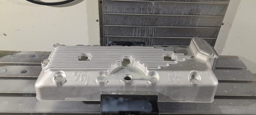
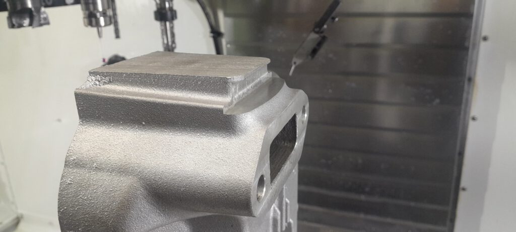
During the first setup, we focus on surfacing the engine block, stud holes, and a bored hole for the electronic ignition centrifugal advance distributor on the top side of the cylinder head.
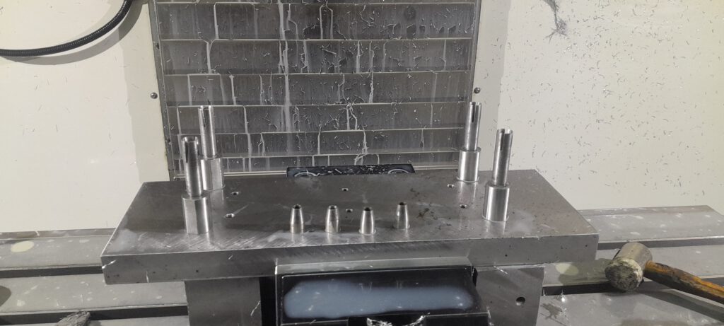
The second setup involves using a plate made by my colleague Frank to line the cylinder head with the existing engine block stud holes. He also made a custom expanding mandrel for easier milling operations on the bottom of the cylinder head.
All these processes can be customized to the customer’s preference. We can use CNC to blueprint the engine for whatever settings it requires, such as lower or higher compression or more volume in the burning chamber. We can also test the engine using a water brake setup for the Model A or Terry Butz engines.
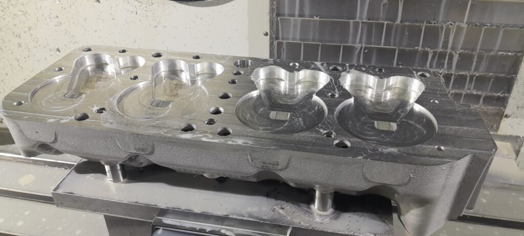
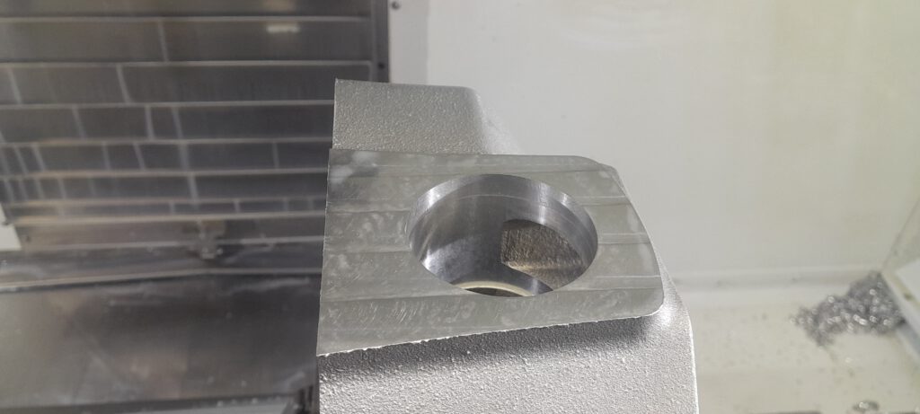
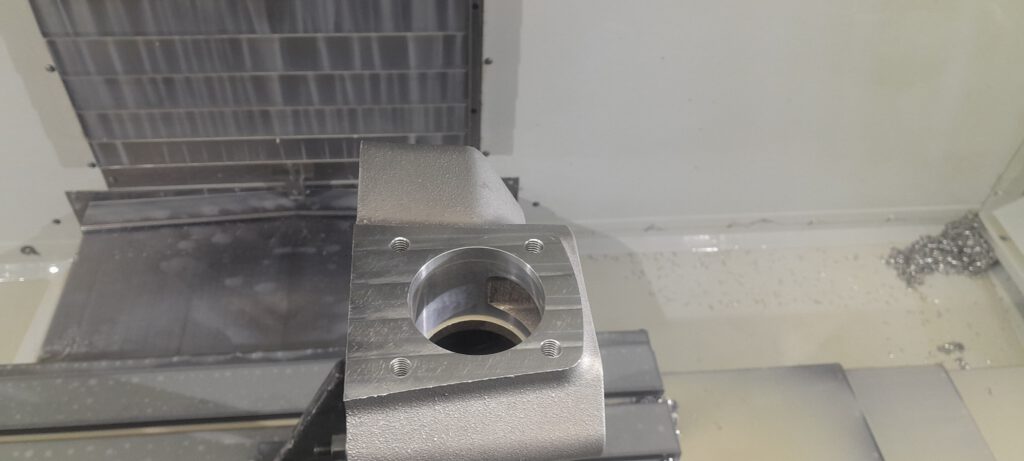
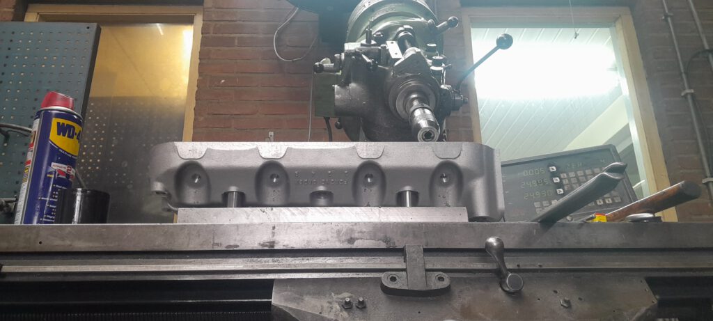
For the third setup, we use an angle plate to set up the cylinder head vertically, allowing us to machine the water pump side. Due to the height, we program the setup to move out of the way for safe tool changes.
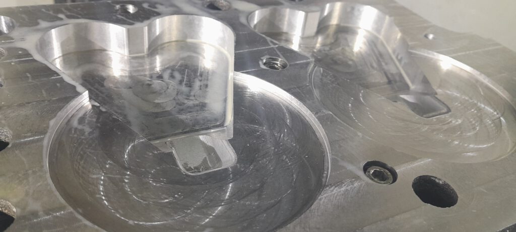
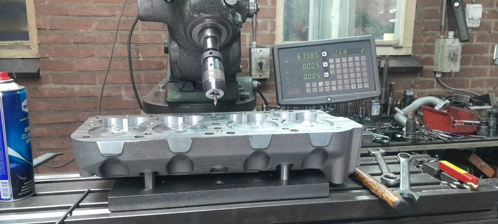
The fourth setup is done on the bridge port by my colleague Frank because I couldn’t make a fixture in the proper angle due to time constraints. We set the milling head at an angle to drill holes through the burning chambers. We then turn the cylinder 180 degrees and mill the other side of the head.


Since we only had two prototyped cast cylinder heads left and were rebuilding the 4th axis, we chose to use the 3rd axis method of machining.
The issue we encountered with the Sparkplug holes was that the vise that could be set at an angle was not trustworthy. Therefore, the fastest way to perform this operation was through conventional milling on the Bridgeport.
Given the opportunity, we would prefer to utilize the 4th axis as it is a more efficient method and requires fewer setups.
Click here! to see how we machined this head using the 4th axis.