I was personally responsible for the design, programming, and machining of this connecting rod, with valuable input and expertise from my father who recommended using C45 for the project. We decided to reinforce the connecting rod because the original one had weakened over time due to wear and tear caused by entropy. My main priority throughout the process has been to ensure the quality of the work, which is why I didn’t take many photos as my focus was on getting the job done right.
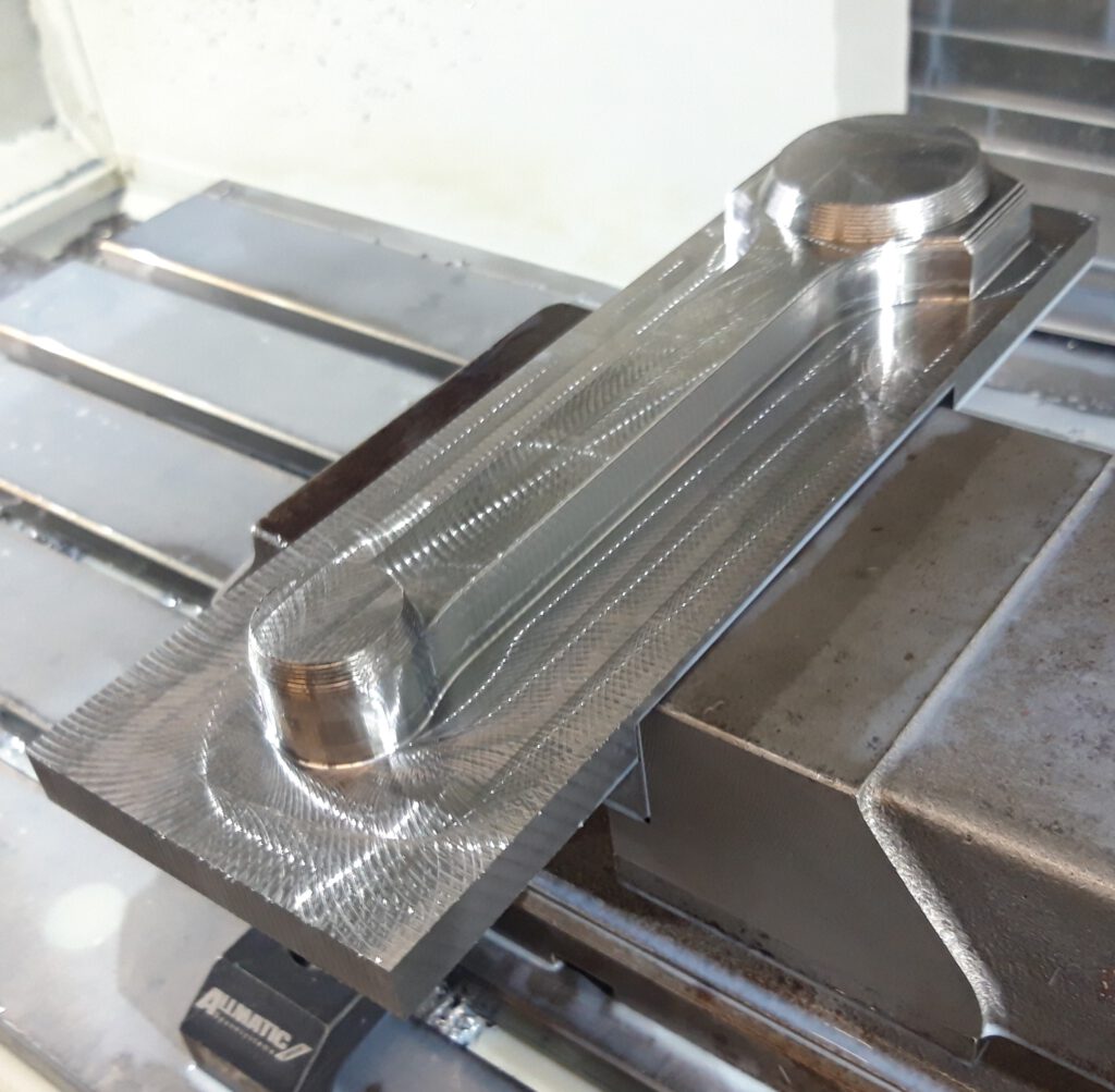
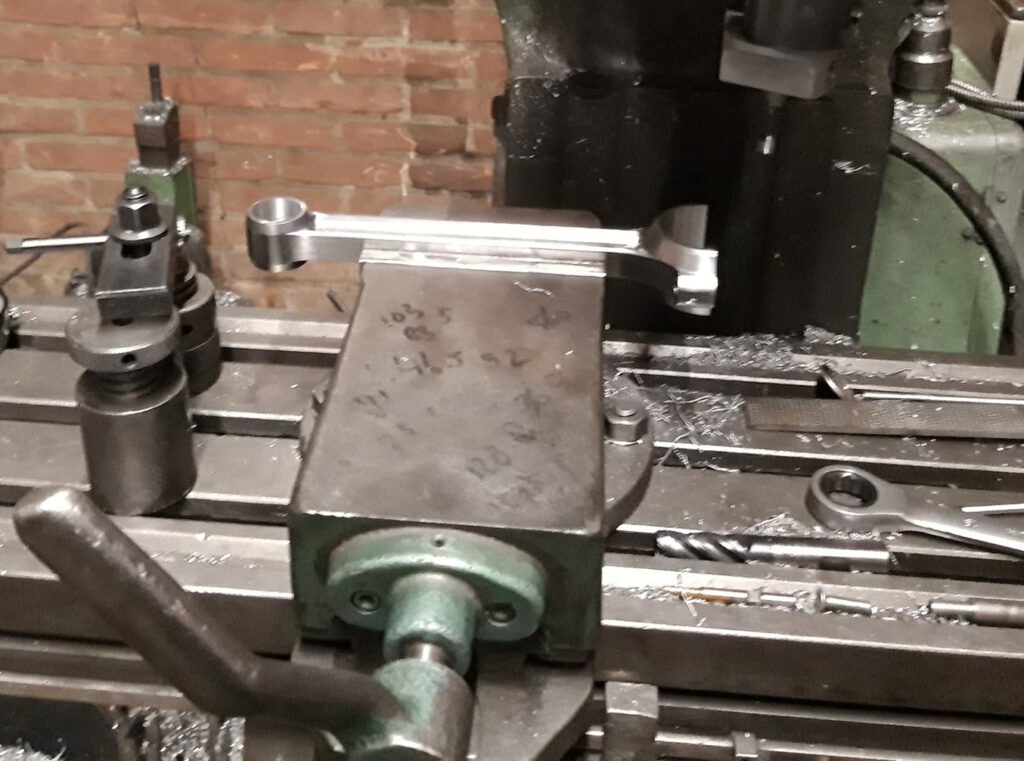
The manufacturing process of the connecting rod involved four machining operations. During the first operation, we horizontally milled a steel block using a hydraulic vise.
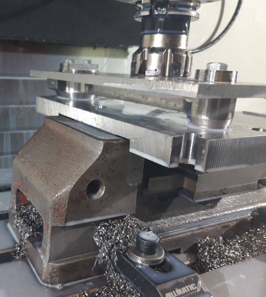
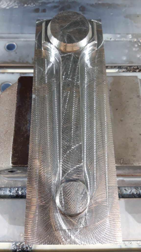
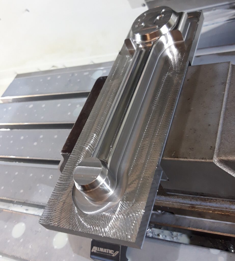
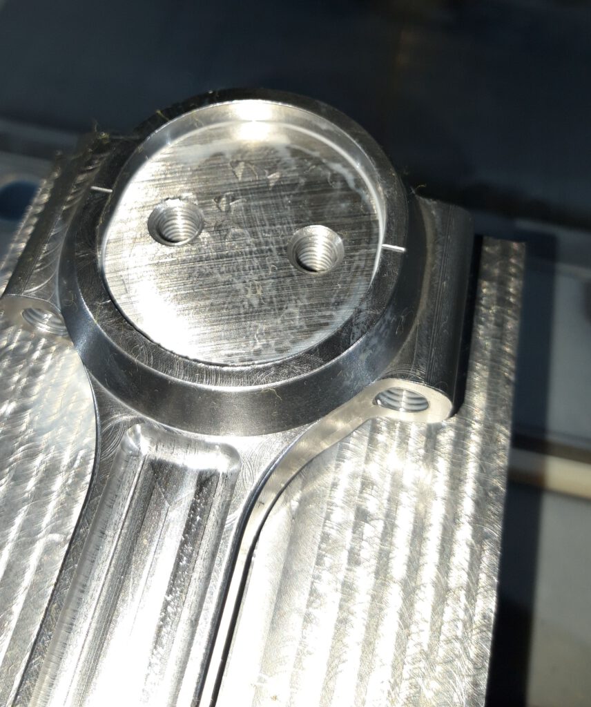
During the second operation, we secured the workpiece in a negative mold, which enabled us to machine the other side of the connecting rod horizontally.
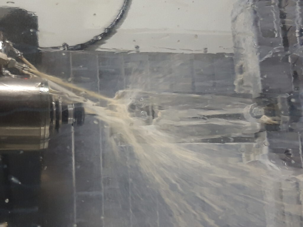
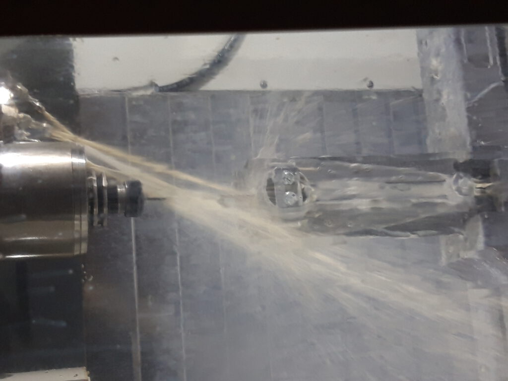
To complete the process, we used a holder that was vertically clamped in the hydraulic vise to make the holes in the connecting rod. We first peck drilled the hole from one side and then flipped the workpiece 180 degrees to peck drill the other side, ensuring that the holes met in the middle of the connecting rod.
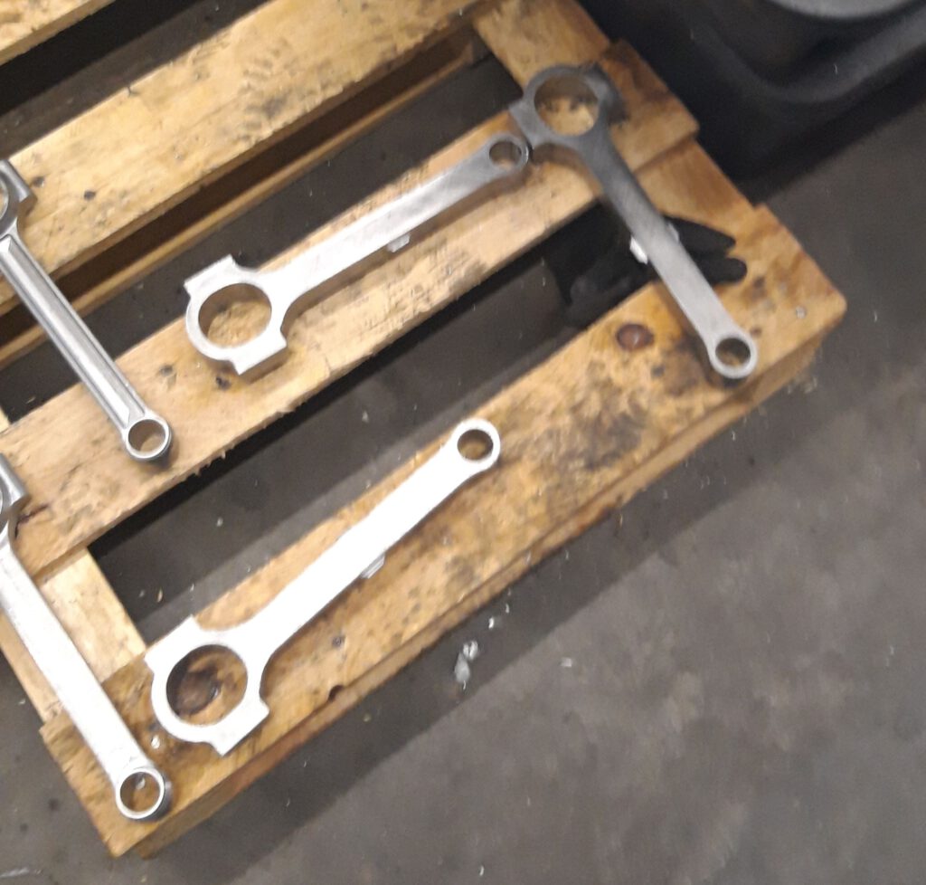
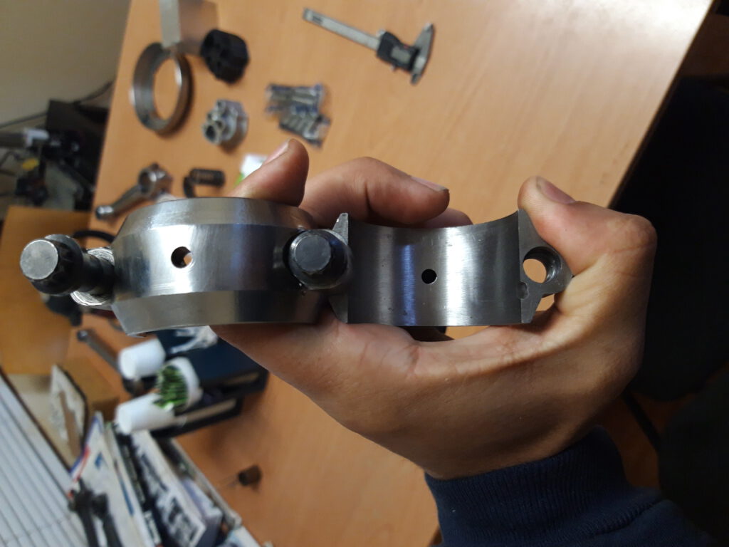
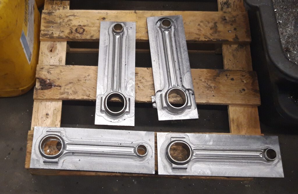
As I am still a novice, my dad helped with the finishing touches. He began by sawing the big end, following the engraved line I created on the surface of the big end using the CNC machine.
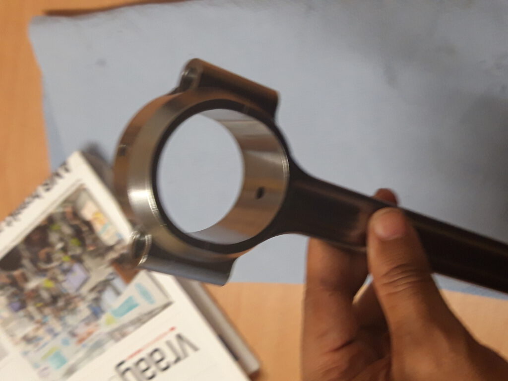
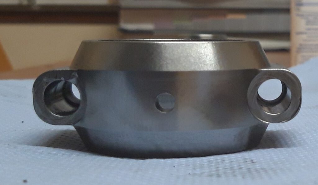
The big end is actually an ellipse with a 5mm space between the two sides. Once he finished sawing, he faced the big end, assembled the connecting rod with the correct torque, and then bored the big end with the appropriate bearing tolerance. He also milled the locating tags so that we could use modern big end bearings.
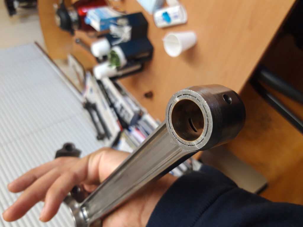
Additionally, he turned a sleeve bearing on the lathe and bored the small end of the connecting rod to the correct tolerance.
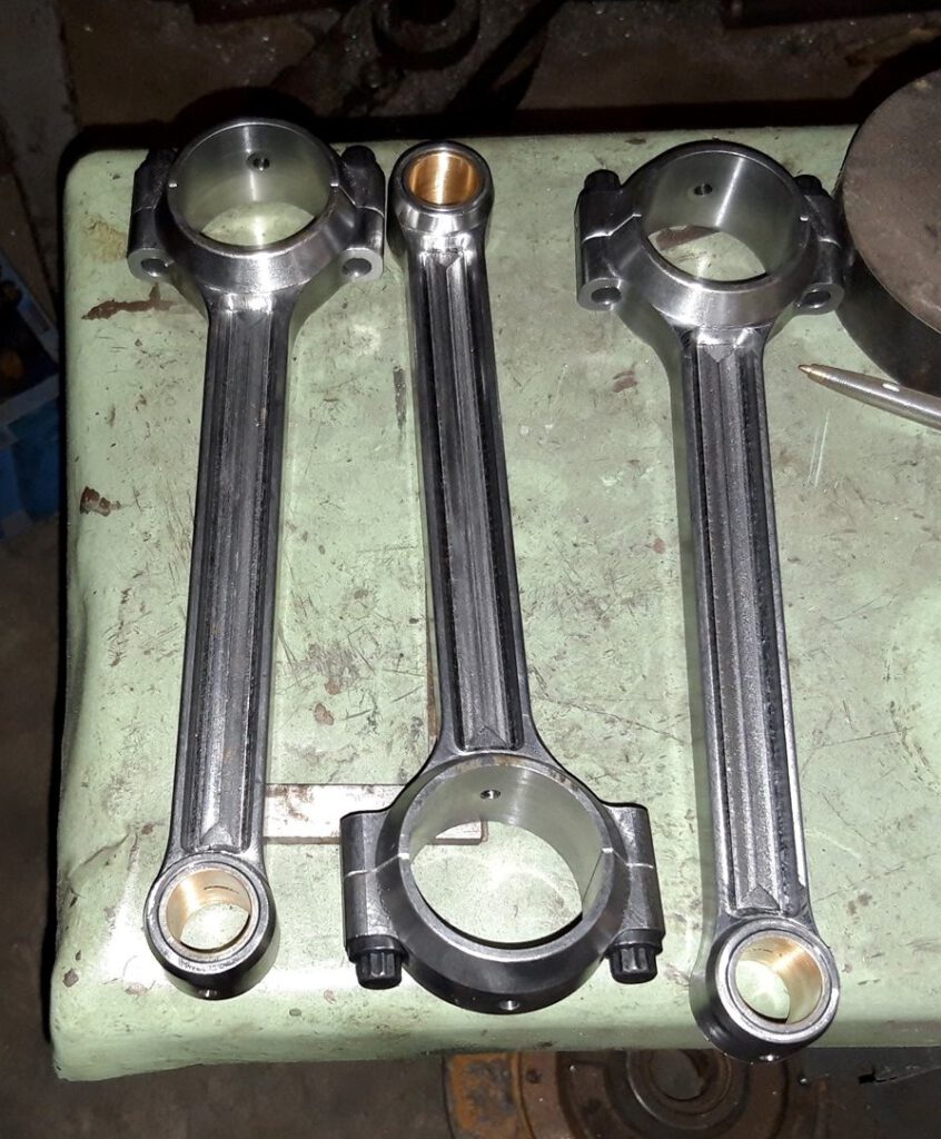
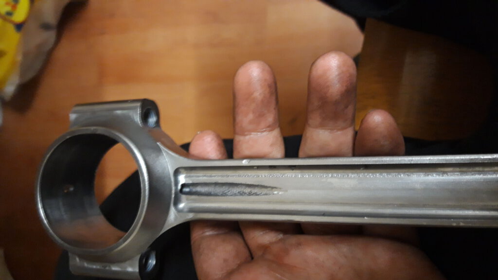
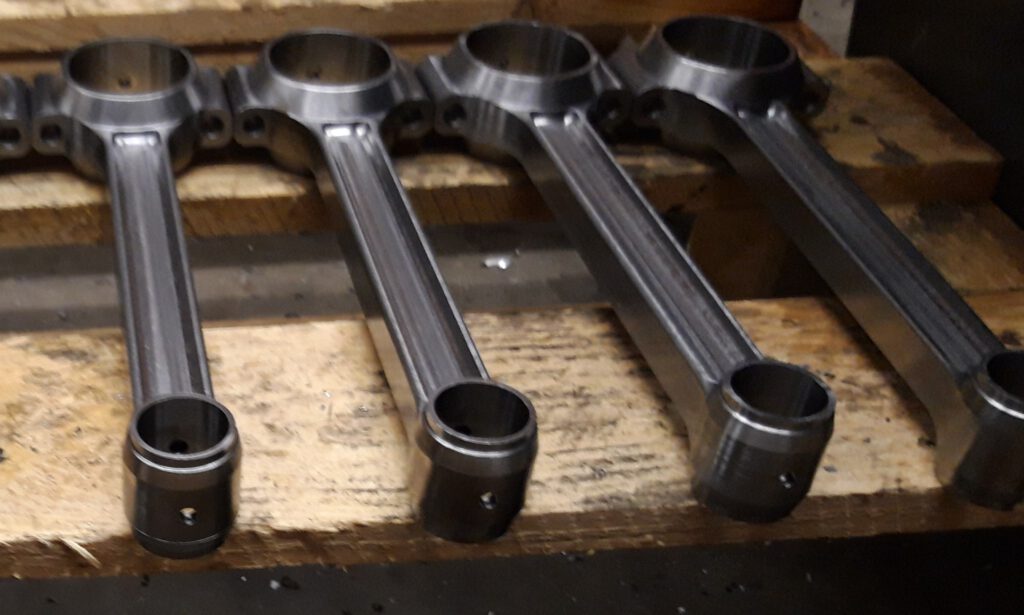
It was a blast creating these Mercedes W18 connecting rods, and my dad showed me some old-school methods for achieving a polished final product.
Stay tuned for more of the connecting rod chronicles because I plan to use a 4th axis to make even more impressive ones in the near future!